Reports 1-1 of 1 Clear search Modify search
IOO (IMC)
rana.adhikari - 21:11 Friday 13 September 2019 (10516) Print this report
IMC Spot Position measurements

We tried measuring the beam spot positions inside the IMC, but it didn't work since it seems some IMC coils are mal-functioning.


During the CARM offset reduction it was noticed by Driggers-kun and Nakano-kun that the carrier power fluctuations are ~25% and the 45 MHz sideband power fluctuations are >50%. This is not there in the single arm locks and so it seems that it must be a problem with the alignment of the PRC optics.

For this reason its important to implement better damping of the payload's 0.3-2 Hz modes using the local sensor damping as well as the optical lever feedback.

We also want to turn on the AS and REFL WFS, but it is clear from Keiko and Stefan's log entries that the beam is too much clipped on the Faraday Isolator after the IMC. Is this due to a misalignment of the IMC? or is it due to the pico motors being in the wrong place?


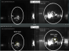
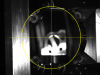
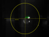
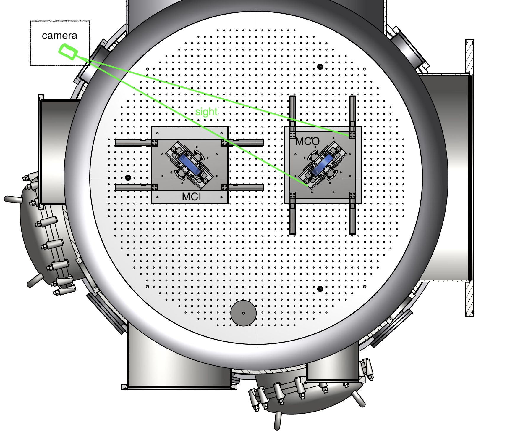
We want to use the STM Pico motors to steer the beam through the Faraday, but first we want to confirm that the IMC spots are centered (especially on MCI and MCO):

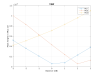
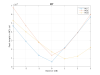
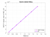
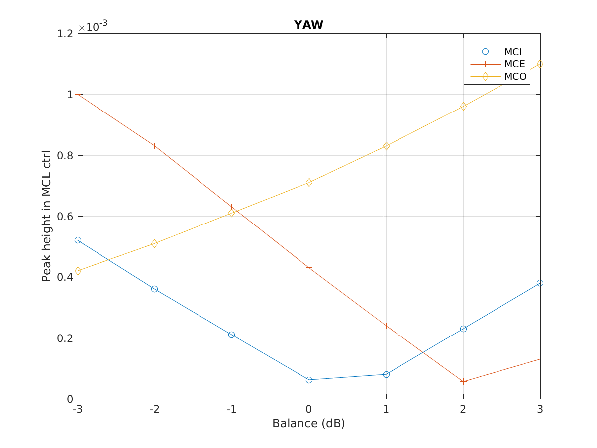
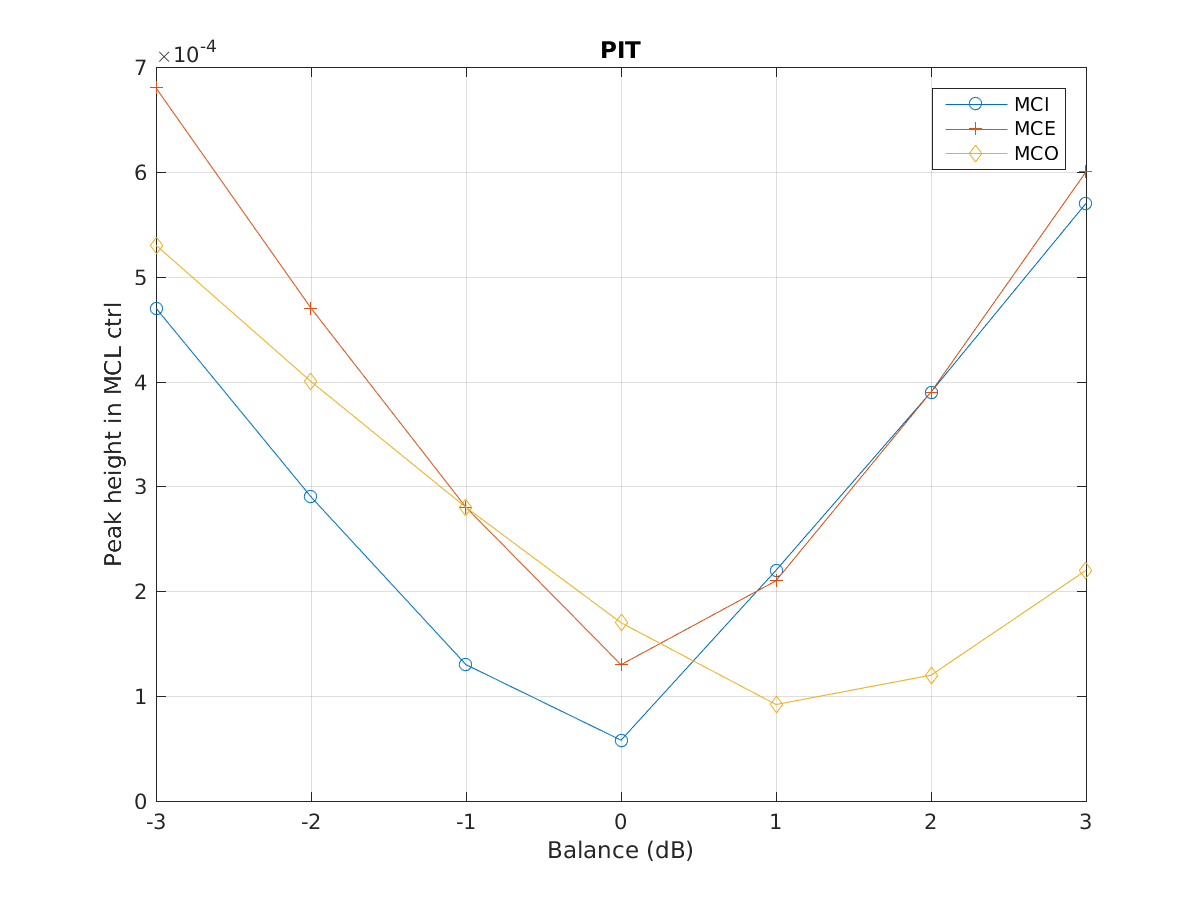
To do this, we undulated the IMC mirrors at ~10 Hz and measured the response in the IMC length readout. If the beam is centered on the mirrors and the coils are equally strong, this would produce no longitudinal motion of the mirror (so far above the resonant frequency of the pendulum). In the attached PDF yu can see the result. Going from low to high frequency, the drives are MCI_P, MCI_Y, MCE_P, MCE_Y, MCO_P, MCO_Y. As you can see, there is ~10x more imbalance in MCE & MCO than in MCI.

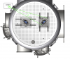
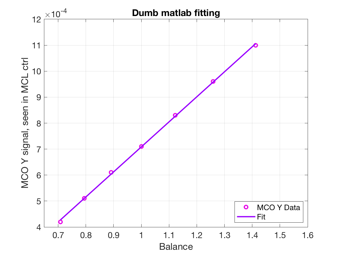
Since there are 4 actuators (H1, H2, H3, H4) and 3 measurements (P, Y, L), we have one extra degree of freedom that can be used. So we drove MCO in the overconstrained ("butterfly") mode that should produce no signal, but it shows up in MCL just as strong as a yaw excitation. Then we drove each coil with a separate frequency and see that the H1 and H2 coils (the ones on the left as seen from the AR side) are 10x weaker than the other 2. We tried triggering the watchdog, but that did not change anything. Nakano-kun suggests that we power cycle the MCO & MCE electronics to see if that resolves the issue.If so, it means that circuit has some broken or marginal trigger logic.

Non-image files attached to this report
Comments to this report:
keiko.kokeyama - 17:19 Monday 16 September 2019 (10541) Print this report

The 10x unbalance must be from somewhere else but the coils since all four coils on MCI, MCO, MCE are all healty. Diaggui data is on /users/VIS/190916/.

MCE
H1 @DC -45 @10Hz -74
H2 @DC -45, @10Hz -74
H3 @DC -45, @10HZ -74
H4 @DC -45, @10Hz -75

MCO
H1 @DC -50, @10Hz -81
H2 @DC -49, @10Hz -79
H3 @DC -49, @10Hz -75
H4 @DC -50, @10Hz -77

MCI
H1 @DC -45, @10Hz -77
H2 @DC -47, @10Hz -77
H3 @DC -47, @10Hz -77
H4 @DC -46, @10Hz -77

unit is [urad/cts]; each coil to oplev PIT channel.

And yes, the beam doesn't seem to be at the center on MCO. It seems to move since this time. MCE is better, and we have no camera for MCI. See the attached photo.
 

Images attached to this comment
keiko.kokeyama - 23:24 Monday 16 September 2019 (10553) Print this report

[RXA, KK]

As shown in the gigE camera image earlier in this thread, the MCO spot position is largely off in YAW (cm scale).


We observed the MCL control signal coupling from mirror YAW (PIT) motion (angle to length coupling) while changing the coil balance of YAW (PIT) from [H1 H2 H3 H4] = [1 1 -1 -1], [1+1dB, 1+1dB, 1-1dBm, 1-1dB] (let's call it 1 dB unbalance), ... to 3dB unbalance. When the spot position and the P/Y tilting center are matched on the mirror, no angular signal should be seen the MCL ctrl signal. We used the lockin osc matrix to apply the balances and actuations.

The result is attached. The x axis is the applied unbalance, which is equivalent to the beam spot distance from the center of ther mirror. The x axis should be calibrated to the spot position from the center, but I couldn't find the distance between the magnets. It will be updated later. The Y axis is the signal in MCL control therefore showing the coupling level from the angular motions. As shown in the plot, MCO YAW is the most mis-centered one.

Looking back the klog, MCO was repaired from the fallen-off magnet and re-installed in May 2018, then the in-air alignment and spot position check was done in June with Stefan. Also, as posted earlier, checked again in September 2018 (klog 6317). I am puzzled how this position change on MCO could have happened. Removal of the MZM path (May 2019) on the PSL table was very careful (checking the MC flash every time we removed a mirror) I don't think that could cause the big input beam misalignment.

Images attached to this comment
keiko.kokeyama - 18:51 Tuesday 17 September 2019 (10573) Print this report

Terrence, Keiko

1. The first attached picture explains the MCO camera position and its sight.
2. The second attached picture is the MCO camera image when we illuminate the chamber from the view port. The shown mirror edge is an estimation by eyes.
3. The third attached picture is the same image, with the MCO oplev SLD off and no illuminator. The beam spot on the mirror is shown. The number is in whatever unit in inkscape.
4. The diameter of MCO is 95.95mm

From above, we assume the MCO beam spot is off for 14mm from the center.

...I remember that I thought I couldn't tell the spot position for +-1cm by the sensor card as the card cannot go too close to the mirror surface when we were checking the positions inside the MCF chamber in air.

Images attached to this comment
keiko.kokeyama - 19:42 Tuesday 17 September 2019 (10575) Print this report

From this plot in this thred, the zero crossing in yaw MCO is at the unbalance of -6.6dB according to my human eye fit. This corresponds the coil matrix for yaw of something like [H1, H2, H3, H4] = [-0.47, -0.47, 2.14 2.14] (left right could be flipped). 

According to this document, the distance between the magnet is 65mm.

So the beam spot should be off for  65*2.14/(0.47+2.14) - 32.5 = 21mm. It doesn't agree with the assumption from the gige camera. Is my calculation wrong? Maybe the center of the mass and the geonetrical center is pretty different because there is wedge? 

keiko.kokeyama - 22:20 Wednesday 18 September 2019 (10596) Print this report
This eye fit is wrong and to be updated.
keiko.kokeyama - 16:20 Thursday 19 September 2019 (10616) Print this report

I fixed the fitting. Michimura-san pointed out that the human eye fit wouldn't work with x (in log/dB) and y (linear). This time, it's matlab dumb fitting instead of human in linear-liner scales.  See the attachment.The zero crossing is at the unbalance of YAW matrix = [-0.2646 -0.2646, 1.7354, 1.7354] (worse), and the assumed position from the center is still ~24mm. Mmm.....is that true?

Maybe we can try Michimura-san's script from his 40m time after JPS?

Images attached to this comment
Search Help
×

Warning

×