Fujii, Miyo
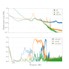
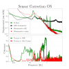
We inject the strainmeter signal into the LVDT actuator on the IP of ETMX. We could compensate the differential ground especially 200 - 300 mHz. (Figure 3).
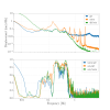
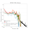
- Xarm length fluctuation when the no sensor correction filters are engaged is shown in Figure2. Top is the amplitude spectrum density (ASD) of displacement of X arm. Bottom is the coherence. The strainmeter is consistent with differential motion of seismometers around 50 - 700mHz broadly. These sensors are masked by selfnoise each other. Above 700mHz, the strainmeter is masked by the noise. Below 50mHz, the seismometers are masked. On the other hand, the fulctuation of the X arm length consistents with the ground motion except the suspension response. The suspension response when the CMRR of ITMX and ETMX is good so that the coupling from common motion of the arm to differential motion of that can be ignored, is plotted in Figure2. There are big peak at 150mHz and 400mHz (Figure2). These peaks also can be seen in Figure1. These peaks are caused by the seismic motion through the LVDT sensors path because of the feedback loop using LVDTs. So, these enhancements can be reduced by the sensor correction.
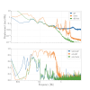
- The X arm length when the sensor correction is engaged is shown in Figure3. The motion of IP stage of ETMX is corrected using the strainmeter signal so that the ETMX moves with ITMX together. It means that the arm length is can be compensate. Anyway, the signal of strainmeter is injected on the sensor correction path of the ETMX with no specific filter, which means filter is just 1. Around 250mHz, we clealy can see the reduction of the arm motion. and also the coherence is reduced. It's so cool. However, above 700 mHz, the noise of the strainmeter enhanced the X arm length. We have to filter out above 70 mHz. Furthermore, the peaks at 150mHz and 400mHz are stil remained. We need to investigate this regidual motion. I think this is caused by ethier the CMR of suspensions or coupling from vertical motion.
- We also could see the compensation of the tidal motion, as shown in Figure4. In this figure, the sensor correction using strainmeter is engaged when -9 minutes. After engaging the sensor correction, the drift of the X arm length is compensate. It's so cool.
Next, we have to some investigation to reduce regidual motion around 150mHz and 400mHz.
And I'm going to run the omicron when this sensor correction is engaged or not.
And I want to implement this filter long time so that some big earthquake can be hit KAGRA. I'll check the reduction when hitting the EQ. Because the strainmter have a very wide sensor range (in principle infinity) and very wide frequency band (in principle, DC), so I think X arm can ride on the earthquake wave. If it's so, It will be cool.
